Without giving away too much of the answer the poorly-worded question implies that an external amplifier circuit will have to be added to the 741 circuit for a combined overall gain of 40 dB at 20 kHz. Using a 741 op amp what is the upper break frequency for a noninverting amplifier with a gain of 20 dB.

Op Amp Gain Bandwidth Product And Frequency Response Youtube
It has two input terminals called Inverting input Pin 2 and Non Inverting input Pin 3.

. Gain margin is the difference between unity gain and the gain at 180 phase shift. Determine the -3db bandwidth if this op-amp has an open-loop voltage gain of Avd100 dB a. F_2 fracGBWA_noise notag.
A 741-type OP-amp has a gain-bandwidth product of 1MHzA non-inverting amplifier using this opamp having a voltage gain of 20db will exhibit -3db bandwidth of A. B of the 741 op amp modeled by lm741mod. F F 100khz V ooT 75µv.
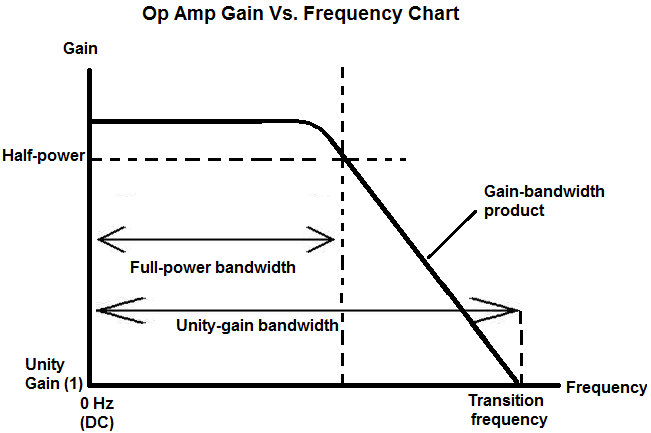
The bandwidth of the op amp 741 is given by the manufacturer as 1 mHz but that is actually the gain-bandwidth product when the gain is 1. Gain Bandwidth Product Unity Gain. For example as shown in Fig3 at 1 kHz frequency the gain of the op-amp is 60 dB 10 3.
This lab will characterize an actual 741 operational amplifier with emphasis on its non-ideal properties such as finite gain and bandwidth. Please see Tutorial MT-033. Therefore the gain-bandwidth product GBP is 1000Hz x 10 3 10 6.
4 above it is graphed for a type 741 op-amp as a function of frequency. 1000 kHz In a certain low-pass filter cut-off frequency fc 35 kHz. To sum it up such specifications especially the high gain rating small output and high input impedances almost guarantees the IC 741 as the most suitable voltage amplifier.
A 741 data sheet shows a typical GBW of 1 MHz. To prepare you for this lab the following preliminary exercises use an assumed non-ideal op amp model that includes finite gain slew rate bandwidth offset voltage and bias current. At some point as we increase the frequency seen at the differential input the open-loop gain will drop down to 1.
P21 The gain-bandwidth product Bandwidth in the data sheet for the LM741 op-amp is about 10 MHz. 0 Hz The most widely used filter in. Its passband is a.
At very low frequencies the open-loop gain of an op-amp is constant but starts to taper off at about 6Hz or so at a rate of -6dBoctave or -20dBdecade an octave is a doubling in frequency and a decade is a ten-fold increase in frequency. At very low frequencies the open-loop gain of an op-amp is constant but starts to taper off at about 6Hz or so at a rate of -6dB. A200000 f o 5hz and supply voltage 15v.
P22 Suppose the source in Figure 23 is the drive waveform to an ultrasonic transducer. A non-inverting amplifier using this OPAMP and having a voltage gain of 20 dB will exhibit a -20 dB bandwidth of This question was previously asked in. Therefore the GBP is 10 6.
10 MHz The LM148 can be used anywhere multiple LM741 or LM1558 type amplifiers are being used and in applications where amplifier matching or high packing density is required. The amplifier is tested in a unity-gain configuration with a small signal applied usually 200 mV p-p. Note that this definition assumes we are using the standard definition for bandwidth.
The unity-gain bandwidth of an op amp is the entire range of frequencies in which an op amp can produce gain. It can provide high gain output. O to 35 kHz d.
Once it reaches its maximum frequency in which it was designed to handle it will then produce no gain at all after this frequency. We can enter either an AC or DC signal to the input. Based on this figure what should be the closed loop 3-dB bandwidth of the follower circuit shown in Figure 23.
Uncompensated op-amps are worth using if you need the added bandwidth and your circuit operates at high gain. Frequency Response of Feedback Network In all of the frequency compensation discussion so far we have assumed that the feedback network has a flat frequency response. Look at Open-loop gain in Fig.
To increase the signal to a higher level to the output. An op amp is able to amplify sound only through a certain range of frequencies. I think you want to use 741 op-amps.
The following are the specifications for the op-amp 741. Voltage follower amplifier can also called as Unity gain amplifier or Buffer amplifier. You must eliminate offset voltage by applying an appropriate compensating voltage to get a proper op amp response 3.
A 741 Op Amp has a gain-bandwidth product of 1 MHz. 5-1 the op-amp that is used in more realistic circuits today does not have infinite gain and bandwidthLook at Open-loop gain in Fig. A 741 type OPAMP has a gain bandwidth product of 1 MHz.
Then it is inversely related to the unity-gain bandwidth of the Op-Amp. Across the decades and among many manufacturers there are lotsa variations of the 741. F F 1000hz V ooT 75µv.
IC 741 is a dual inline packed 8 Pin integrated circuit. A 741-Type OP-AMP has a unity-gain-bandwidth product of 1MHz. Op Amp Unity-gain Bandwidth.
While this is usually the case with the standard resistive voltage divider as. We commonly using IC LM741 as a operational amplifier and the following circuit also designed by using op amp 741. Large Signal Characteristics a Using SPICE plot the step response of the 741 configured as a unity gain buffer see Fig.
A non-inverting amplifier using the above Op Amp and have a gain of 20 dB will exhibit a bandwidth of a. This frequency is referred to as the unity-gain bandwidth. The signal frequency that gives AOL 1 is the unity-gain bandwidth for this op-amp.
When the gain is 2 the bandwidth is 05 mHz and for a gain of 10 the bandwidth is 100kHz etc. F F 1000khz V ooT 75µv. Phase margin at unity gain m is the difference between the amount of phase shift a signal experiences through the op amp at unity gain and 180.
741 Op-Amp Tutorial Unlike the ideal op-amp Fig. The noise gain for a noninverting amplifier is the same as its ordinary gain. The 741 op-amp is one type of solid state.
Converting 20 dB into ordinary form yields a gain of 10. F F 10khz V ooT 75µv. A low level signal is used to determine bandwith because this eliminates the effects of slew rate limit on the signal.
Connection Diagram Figure 1. Bandwidth f F A f F 2000005 1Mhz. On the other end at 1MHz the gain of the op-amp is 1.
Total output offset voltage V ooT V sat A 15200000 75µv. 4 above it is graphed for a type 741 op-amp as a function of frequency. Apply a 10V to 10V step.
Bandwidth Note 6 TA 25C 0437 15 MHz Slew Rate TA 25C Unity Gain 03 07 05 05 Vµs Supply Current TA 25C 17 28 17 28 mA Power Consumption TA 25C VS 20V 80 150 mW VS 15V 50 85 50 85 mW LM741A VS 20V TA TAMIN 165 mW TA TAMAX 135 mW LM741 VS 15V TA TAMIN 60 100 mW TA TAMAX 45 75 mW. They have basic general features as follows. Gain margin 1 - Gain 180 phase shift 11-7 Maximum output-swing bandwidth BOM specifies the bandwidth over.
Op Amp Unity Gain Bandwidth

741 Op Amp Tutorial Op Amps Operational Amplifier
Simulating Gain Bandwidth The Generic Op Amp Model The Signal Archives Ti E2e Support Forums


0 Comments